

Heat Release Calorimetry for Battery Thermal Runaway
Compliance
UL 9540A
The Heat Release Calorimetry, provides a means of determining the burning behavior of the material by measuring specific test responses when the test specimen is subjected to a specified flame ignition.
The test will be conducted in an opening exhaust hood, size in 6000mm by 6000mm, with a well ventilated conditions. The measurement to be made include the rate of heat and smoke release, total heat released, smoke released etc.
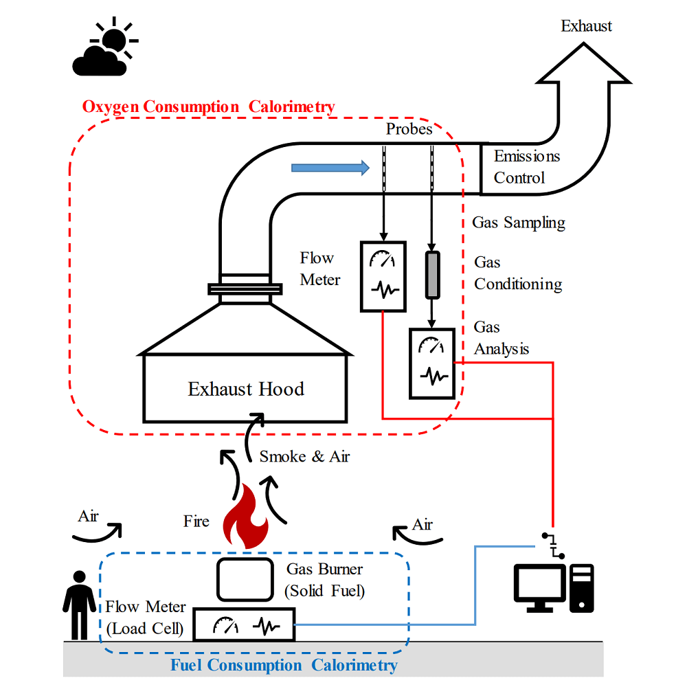
Schematic of Oxygen Consumption Calorimetry (from NIST)
Exhaust Hood and Duct
A stainless steel made hood is installed above the floor, size is 6 meters by 6 meters.
The hood is used to collect the combustion gas and transfer to the exhaust pipe by the plenum chamber on the top.
The side skirt is installed underneath the edge of hood to improve smoke capture, made of glass fibre cloth, resistant to temperatures up to 1100°C.
The exhaust pipe is 1200mm in diameter and 8 times diameter in length.
The hood and duct are connected to the exhaust system that capacity not less than 60,000 m3/h.

UL 9540A Unit Level Test
Instrumental Section
The instrumental section is installed in the end of exhaust duct, equipped with thermocouples, differential pressure transducer, sampling probe, and white light system.
The flow sensors used in the exhaust duct is a bi-directional probe, the probes are made of 316 stainless steel.
The pressure transducer with a range of at least (0-200) Pa and an accuracy of ±2 Pa. Response time of 90% of the output of the pressure transducer is not more than 1s.
Equips 3 OMEGA K type thermocouples for temperature measurement, 24 AWG wire gage, measurement range up to 1000 degrees, accuracy of ± 0.75%.
White light measuring system, consisting of lamp, plano convex lenses, aperture, photocell.
The smoke measurement system is mounted on the integrated measuring section using a flexible joint diametrically opposite each other.
Bar type sampling probe, SS304 made, removable design for easy removal of particles build-up in the sampling probe, reducing system delay time.
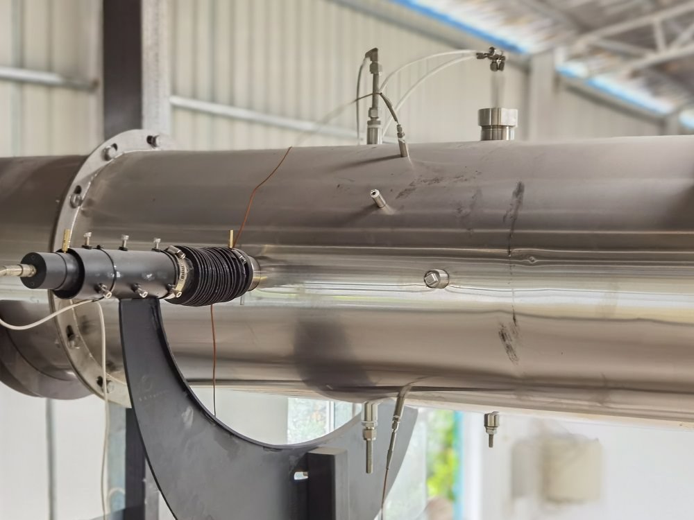
Instrumental Section
Gas Sampling System
Three stages particle filters, 1st: Soot filter, glass fibre cotton, filtering large particles in the combustion gas; 2nd: PTFE filter, filtering rate up to 2 micron; 3rd: PTFE membrane, filtering rate up to 0.5 micron, effective moisture isolation.
Compressor cold trap, cool capacity up to 320KJ/h, temperature control accuracy up to 0.1 °C, static variation 0.1 °C, self-starting and maintenance-free.
Steam trap, automatic drainage of the cooling water generated by the cold trap, maintenance-free.
Dry the residual moisture in the sampling gas, with quick disassembly and replacement of the drying medium.
KNF vacuum sampling pump with a sampling capacity of 40 L/min, continuous sampling pressure of 50 KPa, high gas tightness, low noise and low vibration.
Gas Analysis System
SERVOMEX or ABB paramagnetic type O2 analyzer, measurement range of 0 to 25%, accuracy of ± 0.01%.
SERVOMEX or ABB NDIR type CO analyzer, measurement range of 0 to 1%, accuracy of ± 0.001%.
SERVOMEX or ABB NDIR type CO2 analyzer, measurement range of 0 to 10%, accuracy of ± 0.01%.
Calibration System
Sandbox burner, provides an even gas flow over the top.
Remote-controlled ignition device, pilot flame ignition with sparker.
Mass flow controller for flame source control, accuracy up to ±2%.
Auto flow control software.
Data Acquisition System
Gas concentration: 100×10-6;
Temperature: 0.1℃;
DPT: 0.1Pa;
Time: 0.1s;
Other signal: 0.1% of F.S.
Windows Software
Windows base operation software, interface in English.
Function includes, sensor monitoring, sensor calibration, system calibration (step calibration), heat release test, report export and management.

System Step Calibration


