
Brandschacht Test Apparatus
Compliance
DIN 4102 Part 15, DIN 4102 Part 1.
Brandschacht Test Apparatus, in accordance with DIN 4102 Part 15, is designed for the fire testing of building materials and elements. The ‘brandschacht’ is a square chamber, which has a constant flow of air introduced from the bottom, and combustion gas escapes from the top of the chamber. The specimens are mounted vertically and exposed to the flame generated by a square gas burner.

(Picture from DLAB)
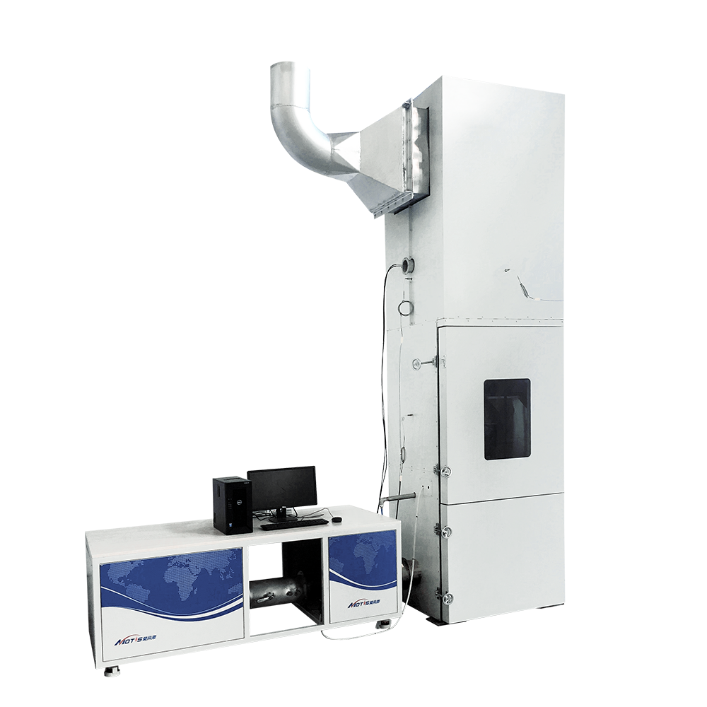
The Brandschacht Test Apparatus consists of:
The ‘Brandschacht’ has an interior size of 800mm by 800mm by 2000mm.
The chamber wall is a multi-layer structure, composed (from interior to exterior) of 2mm steel sheet, 6mm ceramic felt (density not exceeding 600kg/m3), two 40mm thick mineral insulation fibre (nominal density 100kg/m3), and steel sheet.
The chamber from bottom to top are the inlet chamber, air regulator, combustion chamber, measuring section, and outlet.
The inlet chamber is introduced with an air of constant rate and temperature through a duct of φ200 on the right side.
A constant temperature inlet system capable of providing a constant flow of air at a flow rate of 10±1m3/min and a temperature of 23±2°C.
An inlet chamber fitted with a type K insulated thermocouple for measuring the temperature of the inlet air with an accuracy of 0.1°C.
Air stabilizer, set above the inlet chamber, consisting of a porous steel plate and multiple layers of glass fibre felt, to homogenize the inlet airflow.
A combustion chamber to house the burner and the test stand, which is a rectangular frame 1000 mm high with screws on all four sides to adjust the mounting distance of the specimen
A square burner in the size of 200mm by 200mm, with combustion nozzles evenly distributed on all four sides and nozzle openings of 3.5 mm diameter, capable of providing a uniform jet flame.
A gas control system, consisting of a pressure reducing valve, pressure gauge, solenoid valve, mass flow meter, and electric spark igniter.
Equipped with a methane mass flow meter and an air mass flow meter to control the gas flow with an accuracy of 2%.
Equipped with a high voltage electric spark igniter for remote ignition of the flame source.
Equipped with a lower door outside the inlet chamber for maintenance.
Equipped with an upper door outside the combustion chamber for specimen installation, tempered glass on the door for observation.
The measuring section is fitted with a T-pressure measuring tube and thermocouples.
A T-type pressure measuring tube connected to a micro differential pressure sensor, with software for realistic pressure in the chamber in real-time.
Omega® type K stainless steel insulated thermocouples with a resolution of 0.1 degrees.
Square duct, located at the top of the combustion chamber, with the lower part connected to the combustion chamber and the upper part connected to the external exhaust system.
A hot-wire anemometer, measurement range 0-10m/s, resolution of 0.1m/s, for air flow calibration.
Data acquisition system, record the data of temperature, airflow, and time.
Standard operation software, with the function of system monitor, system calibration, gas control, standard test program, and test data & report management.